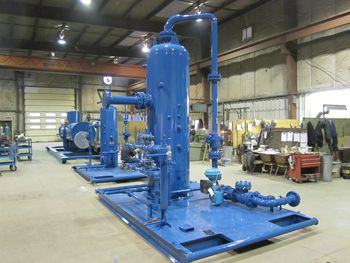
Fabrication:
We build and package a wide range of standard separators as stock units:
Vertical Separators
- 16” through 36” diameter
- 250 through 1440 PSIG DP at 100 °F
- Sweet and Sour Service
Horizontal Separators
- 36” through 48” diameter
- 1440 PSIG DP at 100 °F
- Sweet and Sour Service
Custom Separators
We can custom package most size vessels to a customer’s specifications.
Inventory:
We maintain an inventory of separator packages, including most of the standard sizes described above. All equipment inventory is available for Sale, Rent or Rental Purchase.
Separator Terminology:
 Separator Components:
The function of a separator is to provide removal of free gas from oil and/or water at a specific pressure and temperature. For efficient and stable operation over a wide range of conditions, a gas-liquid separator normally has the following features:
- Primary Separation Section – This section is for removing the bulk of the liquid in the inlet stream, liquid slugs and large liquid particles, in preparation for the second step of separation. To do this, it is usually necessary to absorb the momentum and change the direction of flow by some form of inlet baffling.
- Secondary Separation Section – The major separation principle in this section is gravity settling of liquid from the gas stream after its velocity has been reduced. The efficiency of this section depends on the gas and liquid properties, particle size and degree of gas turbulence. Some designs use internal baffling to reduce turbulence and to dissipate foam. The baffles may also act as droplet collectors.
- Liquid Accumulator Section – The liquid(s) is (are) collected in this section. The liquid should have a minimum of disturbance from the flowing gas stream. Sufficient capacity is necessary to allow for surges and to provide the retention time necessary for efficient separation of gas breaking out of solution and separation of free water from oil in three-phrase separators. A vortex break may be located over the liquid outlet nozzle(s) to prevent gas or oil entrainment with the bottom liquid.
- Mist Extraction Section – The mist extractor of the coalescing section can be one of several designs (a series of vanes, woven wire mesh pad or centrifugal device). The mist extractor removes from the gas stream the small droplets (normally down to 10 micron diameter) of liquid before the gas leaves the vessel. Liquid carryover is normally less than 0.1 gallon per MMSCF.
- Process Controls – The operating pressure is controlled by a pilot operated gas back pressure valve. Where the gas is being delivered to a pipeline the minimum separator pressure is usually set by the transmission or gathering system pressure. Separators should be equipped with one or more liquid level controls. Usually a liquid level control for the liquid accumulation section of two-phase separators activates a liquid dump valve to maintain the required liquid level. Two liquid level control systems are normally used for three-phase separators. Internal weirs and baffles are used in conjunction with these liquid level controls. Separators are equipped with gauge glasses or sight glasses to indicate one or two levels. A pressure gauge and thermometer well are usually installed on separators.
- Relief Devices – All separators, regardless of size or pressure, shall be provided with pressure protective devices and set in accordance with ASME Code requirements. The relief valve is normally set at the maximum allowable working pressure (MAWP).
Options:
When specified by the purchaser, separators may be equipped with other controls and accessories such as the following:
- Inlet shut-in valve
- Pressure sensor or control
- Level sensor or control
- Temperature sensor or control
